Mechanical Engineering
Topology Optimized Bridge
I worked with a small team of five in an additive manufacturing course to create a lightweight PLA FDM bridge. I took this opportunity to refine my methodology in topology optimization. My team came up with a few simplified bridge designs and I ran each through topology optimization software to see what geometric inputs have the most success. I then iterated upon the most successful designs with further optimizations to find the strongest and lightest solution.

To best create an optimized bridge, each team member modeled a simplified bridge that I ran through the topology optimization software. I submitted simple block designs, under the assumption that the more material the optimization software could work with, the better.


I ran each of these designs through Altair Inspire Topology Optimization with a goal set to optimize to a certain mass, such that all the bridge designs were the same mass in the end. From there, the FEA revealed that the strongest option. (See option in box)
I then ran this bridge through the optimization two additional times with the end goal of a specified safety factor. Once I warped the mesh output in NURBS and edited the form in Solidworks, the structure to the left was created. FEA was performed by making the solid into a shell to approximate the low infill of the final part. Anisotropic stress properties were examined with each principle stress output and compared to tested material values.
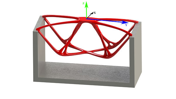
The structure was then exported, and printed in the X-direction facing up. Once post processing was complete, the bridge was tested and proved its theoretical strength.